Modular House

  • Type of project: Architecture Technology and Construction Management, Prefabricated
  • Year: 2021
  • Software Used: Revit, Photoshop

The Project:


In this project, we designed a standardized modular system that can be used in the growing market of small and tiny sustainable house units in Denmark and Northern Europe.

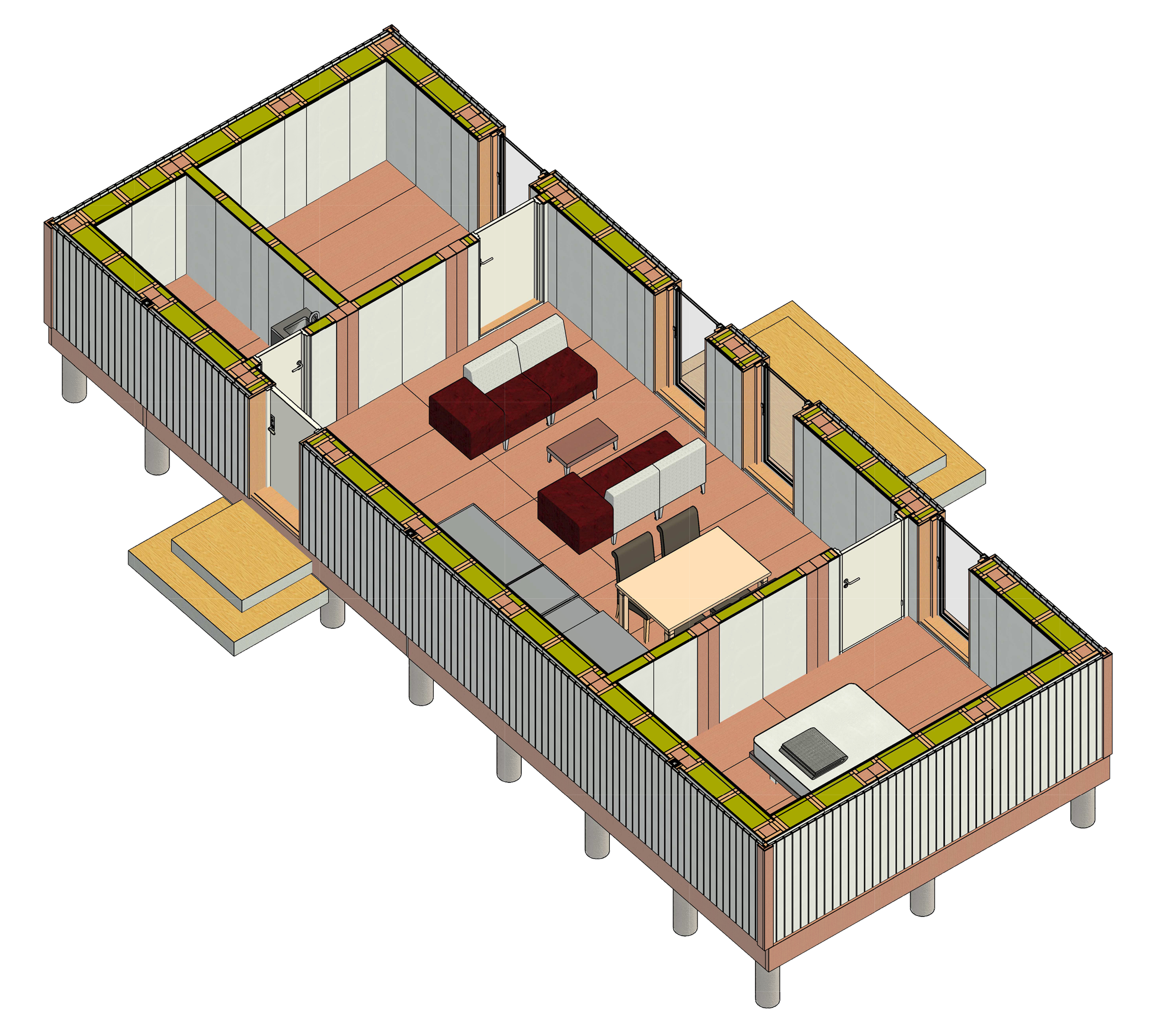
Because we wanted to have the option to make different configurations and arrangements of the modules, our concept of a module was to design “half modules”. We designed and sized them so they can be positioned and combined in stacks of 2, 3, 4, etc., a module being 1500x4500x3000 mm (approx. half of a room). For example, a regular bedroom can be made of 2 modules, but it can also be extended to 3, or a living room can be made by combining from 2 until 5 modules, according to what is the most important for the person/family that will use that house.

As we wanted our modular system to fit as many scenarios as possible (terrain, climatic, aesthetic, etc.), we chose a foundation that was lifted from the ground. We used mainly timber frame structure and timber cladding and in order to have a high degree of flexibility regarding the architecture and possible client’s wishes for personalization, we designed a frame of the module consisting of columns and beams that can be completed afterwards with a variety of wall, floor and roof elements chosen by the client who ca participate and decide on different possibilities of arranging the modules and the overall layout of the house.
Administration & Production Building

  • Type of project: Architecture Technology, Construction Management, New Industrial Building, Prefabricated
  • Year: 2022
  • Software Used: Revit

The Project:

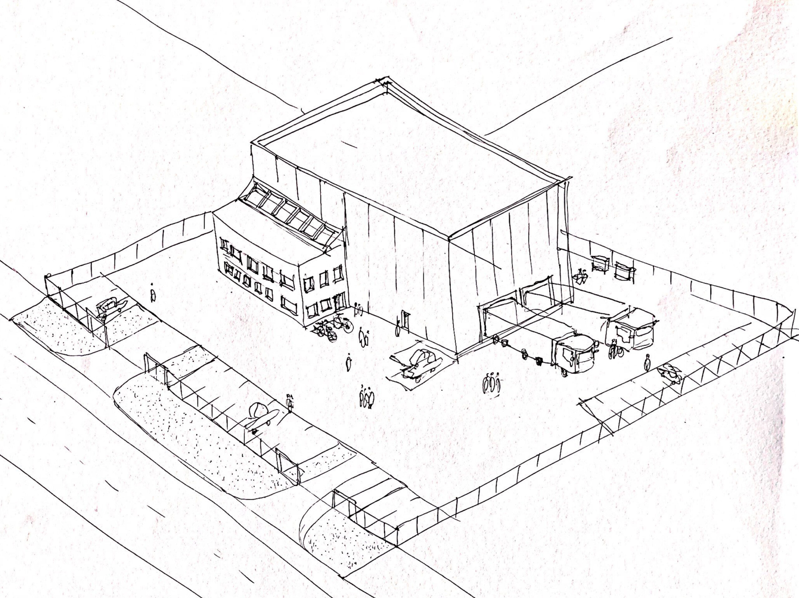
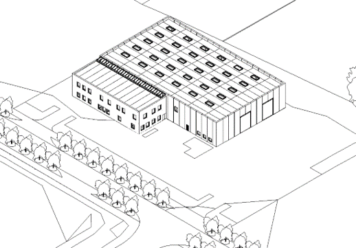
During this project, I acquired knowledge about industrial production and construction method. A big objective was learning how to work with prefabricated construction and to prepare the tender material for a turnkey contract. Because we worked with prefabricated elements, an
Early Tender phase was prepared right after the Outline Proposal we received from the client. The groups were acting as total consultants for the client and we divided our work by assigning roles. Therefore, my roles were MEP (Ventilation), Architect, Landscape Architect and ICT Manager.

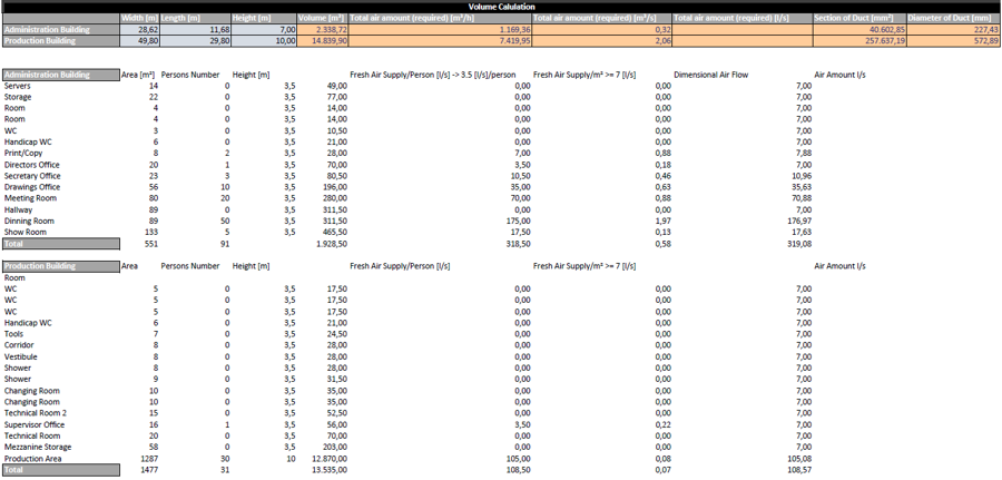
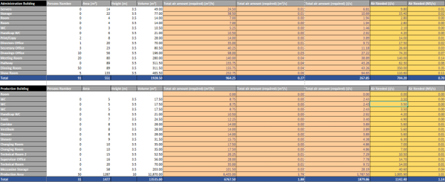
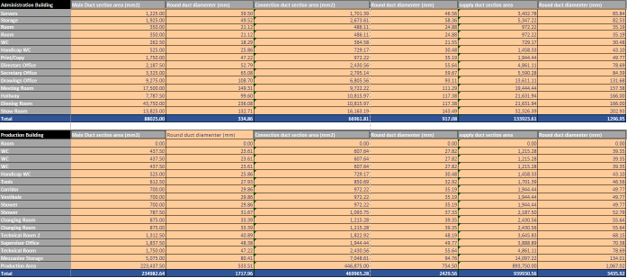
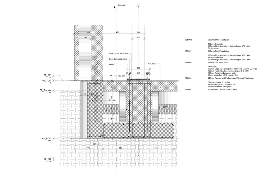
As part of my responsibilities, I prepared the main drawings after I 3D modeled the buildings, the landscape and the ventilation model using Magicad. The results are presented in the following pages. I have also prepared the site plan, did the extension and ventilation calculations, worked on fire plans and energy framework. For my individual, I focused on foundations and cladding, as it will be visible in the detail drawings presented below.

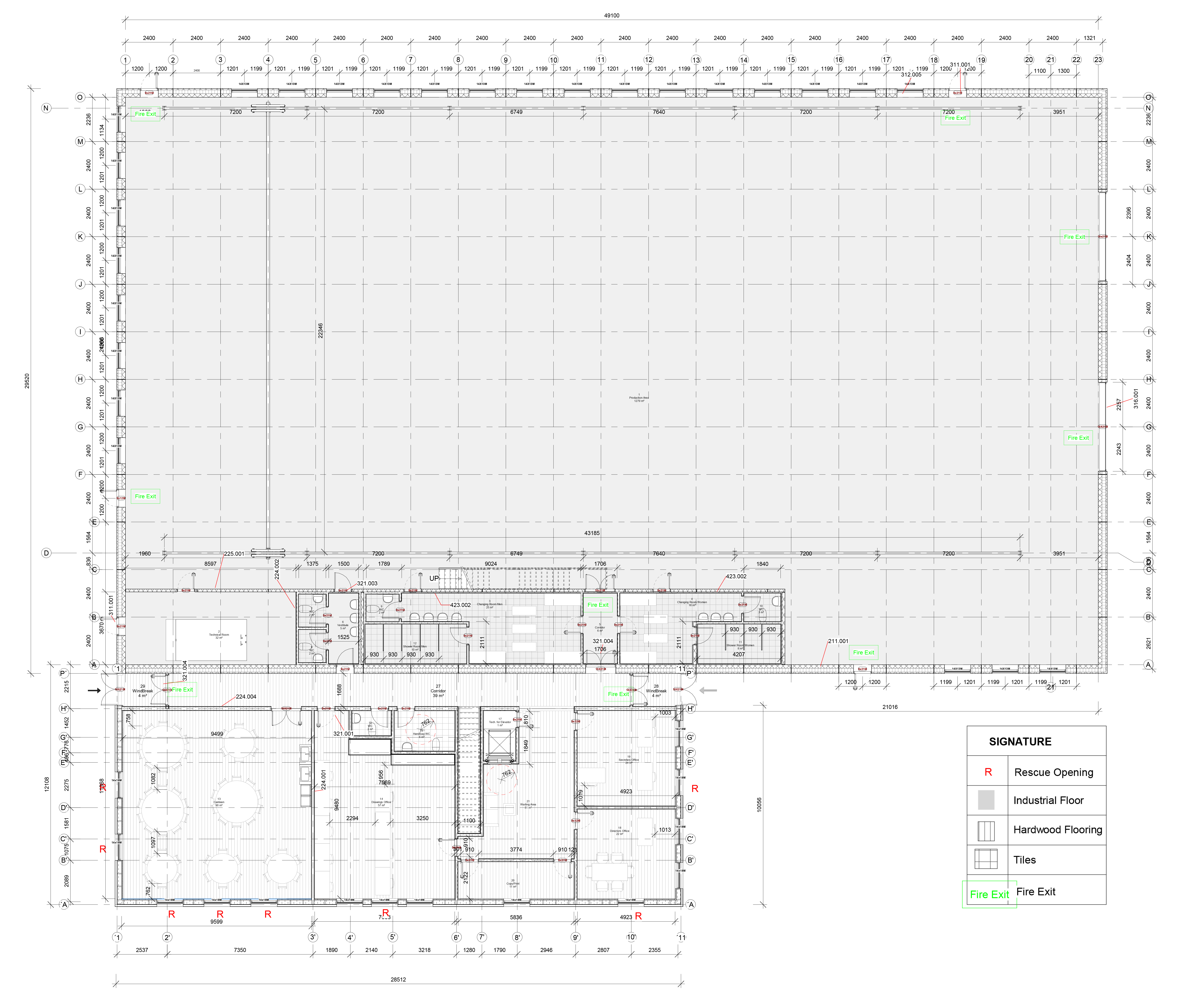
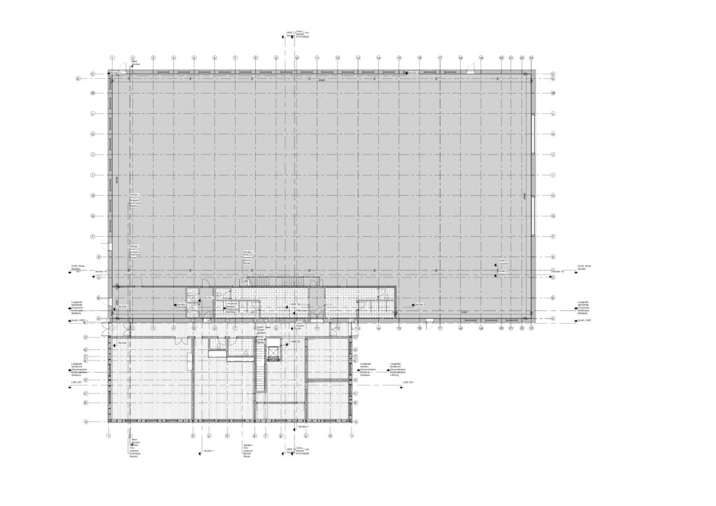
Ground Floor
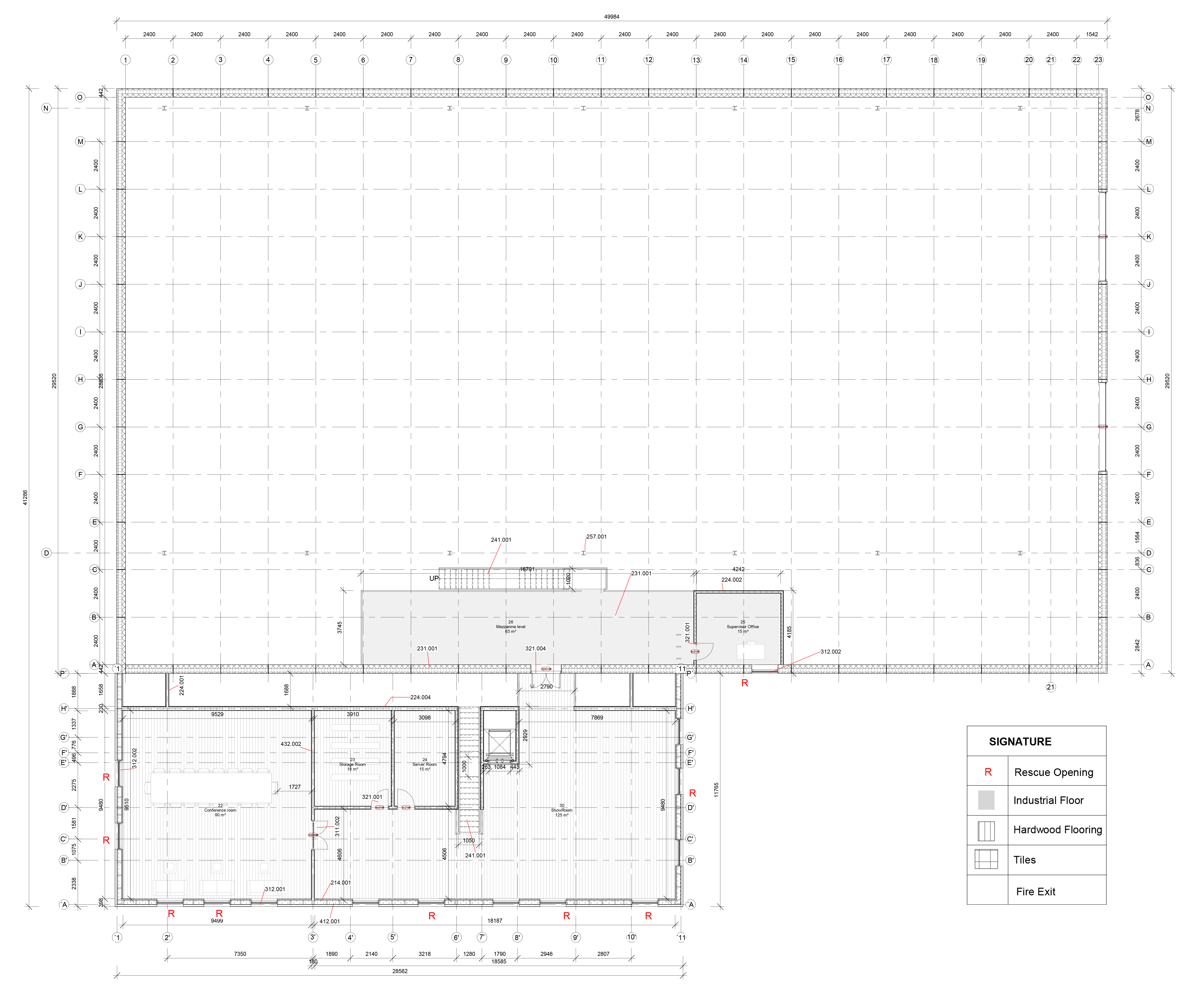
1st Floor

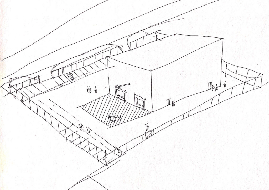
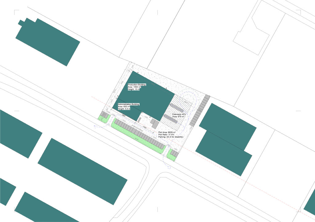
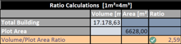
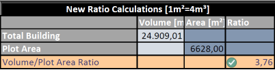
We decided to position the building so that it would be possible to extend it in the future, as this was a request from the client. I followed the guidelines from the Local Plan, BR18, SBI and Parking Strategy for Odense and designed a 5 meters wide green-belt, 44 parking spaces (4 of them for disabled people) and left room for an extension of 45% as the building was located in the EA industrial area – allowed to build on maximum 60% of the plot and volume may not exceed 4 m³/m².

Site Plan
Volume Calculation
Ratio Calculation
Extension and Building Volume Calculation
New Ratio Calculation
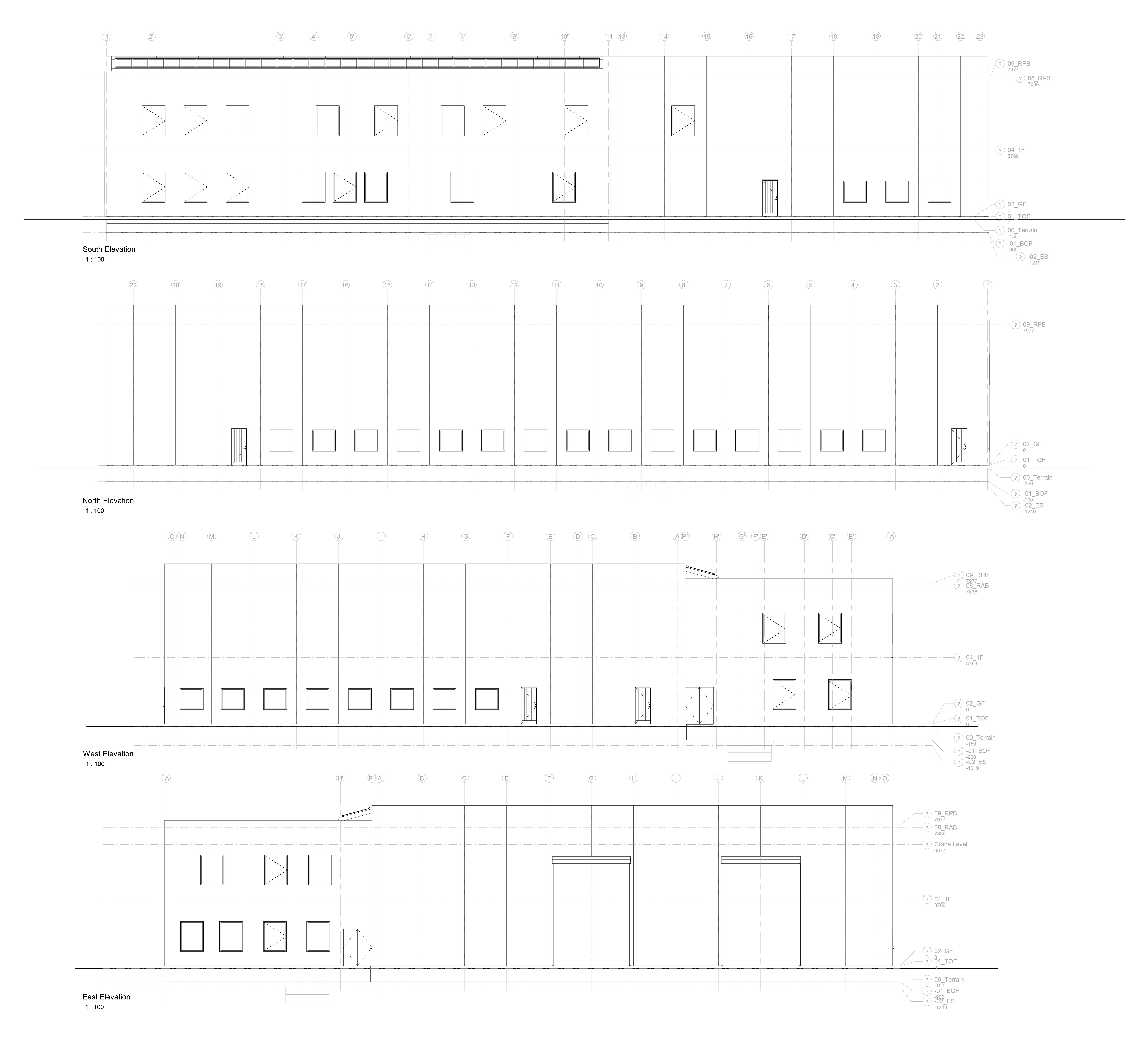
Elevations
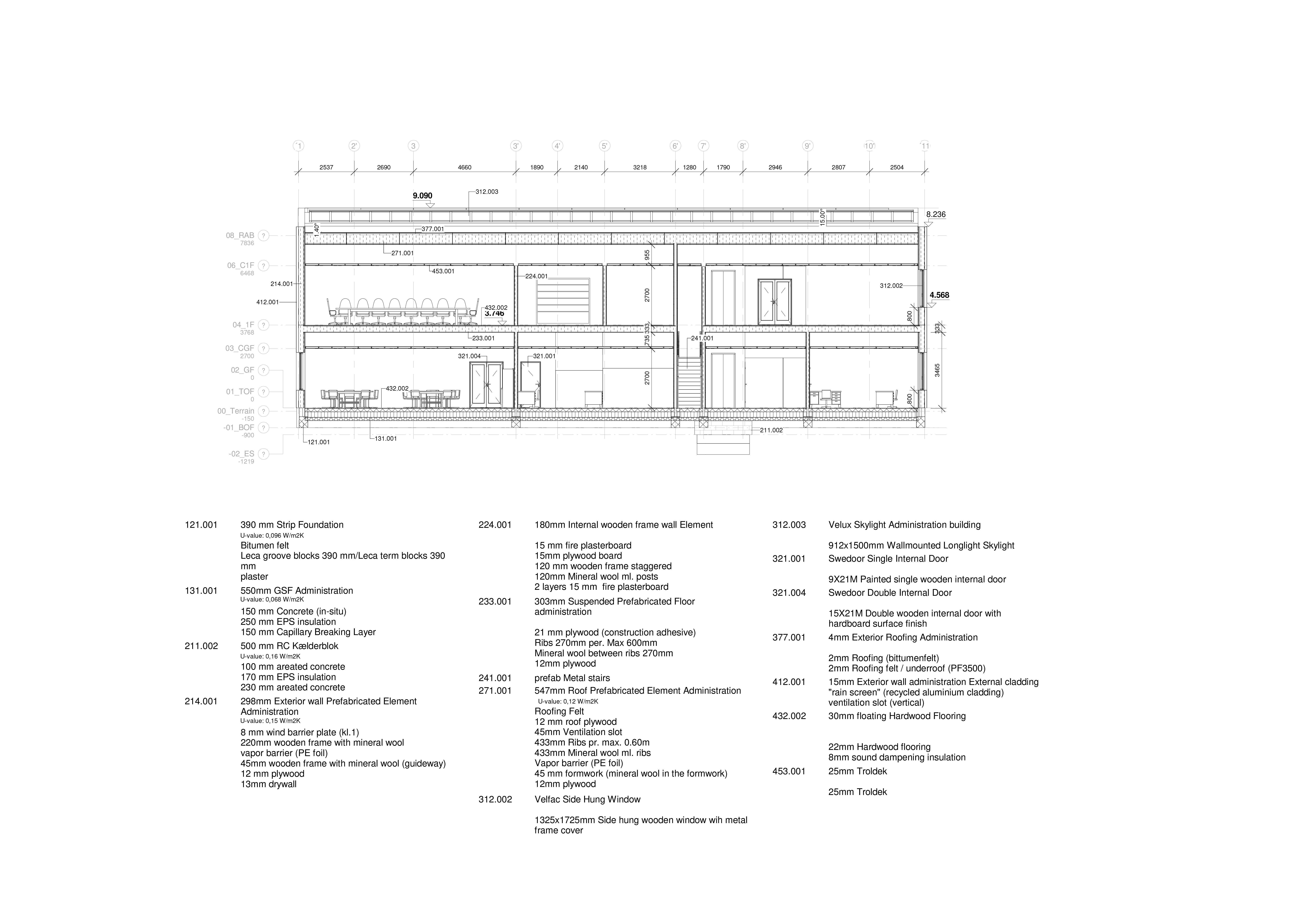
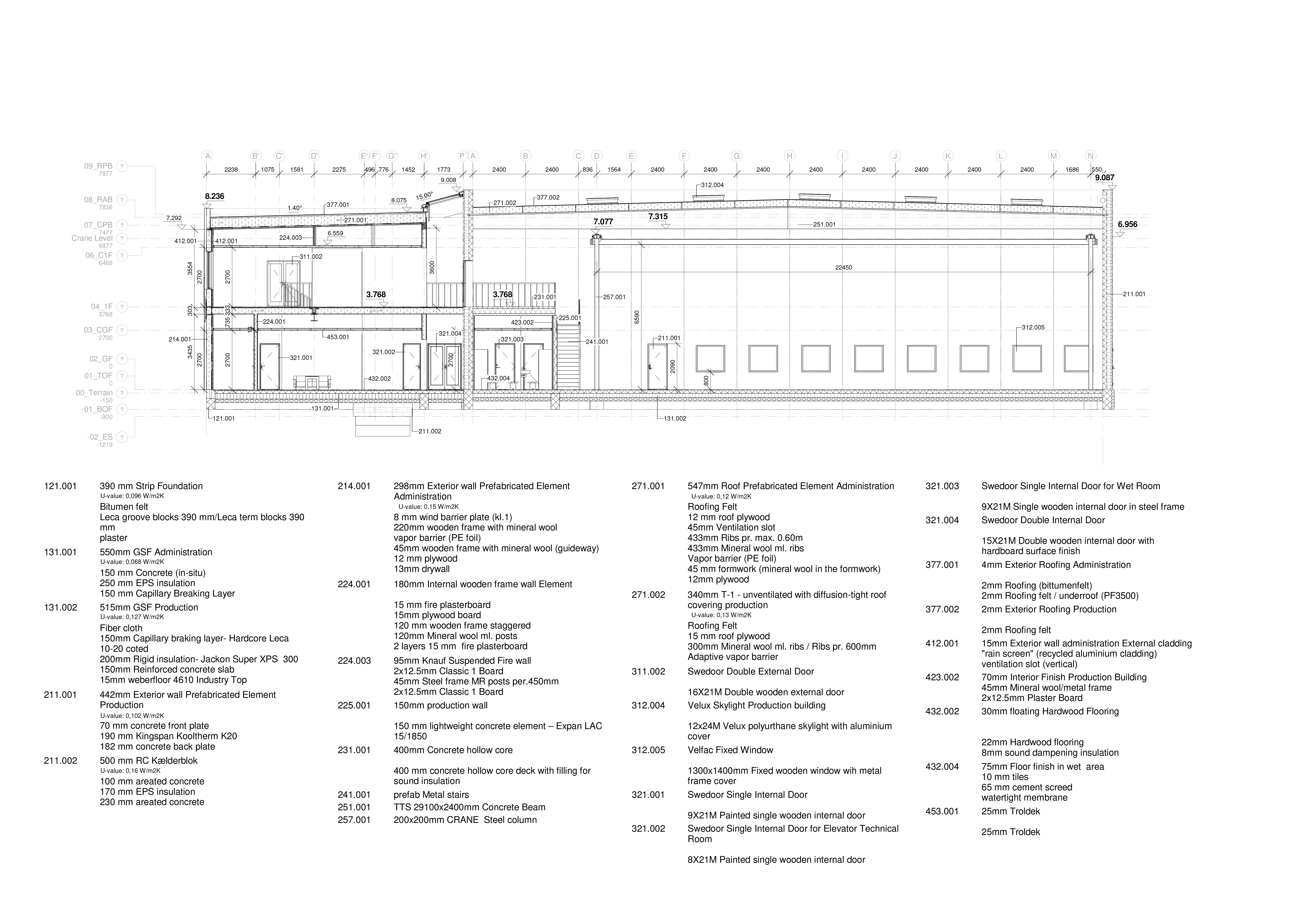
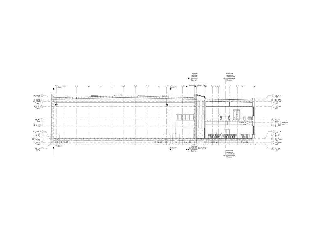
Longitudinal Section Administration Building
Cross Section
Longitudinal Section Production Building
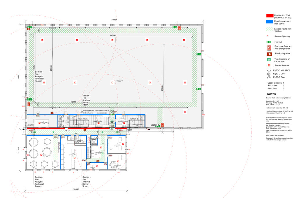
Ground Floor - Fire Plan

Notes:
Exterior Walls not exceeding 600 m²:
Insulation:B-s1, d2:
Cladding: K1 10/ B-s1,d0
Rain screen: D-s2,d2

Exterior walls exceeding 600 m²:
Surface Cladding class: K1 10/B- s1, d0
Rain screen: Class B-s1, d0

  • Fire Hose Reels and Extinguishers – the distance from any given point to the nearest hose reel does not exceed 25 m (see the dashed red circles with radius 25 m).
  • Walking distance from any point in the fire cell to an exit does not exceed 44m rule.
  • ABV system with skylights.
  • Fire safety of ventilation ducts in section walls: BRS fire damper system
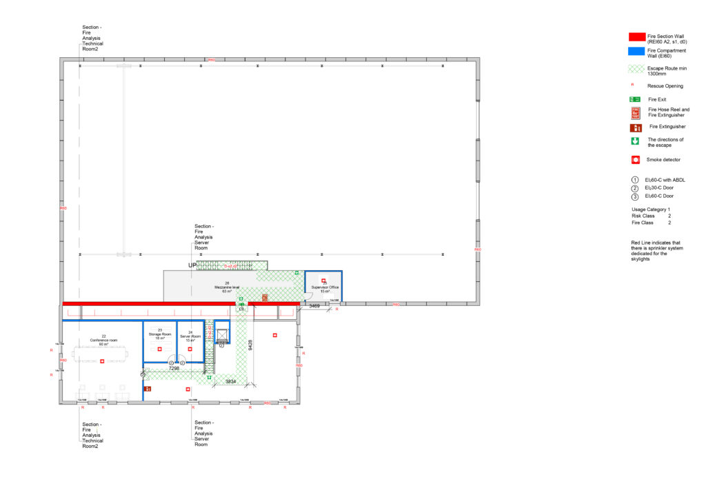
1st Floor - Fire Plan
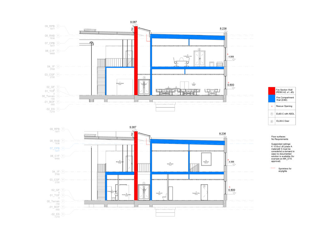
Fire Sections
General Ventilation Calculation
Specific Ventilation Calculation
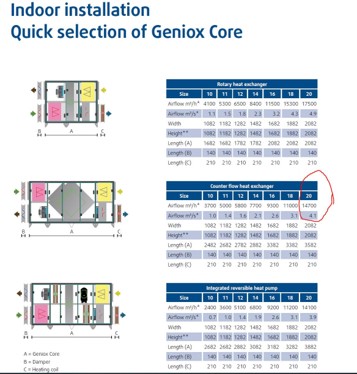
Selection of Ventilation Unit


3D View Ventilation
3D View Ventilation
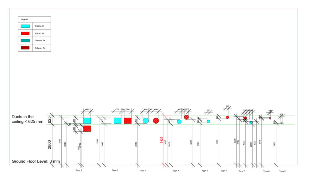
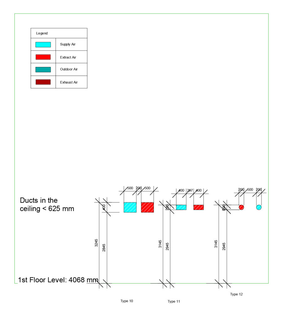
Ventilation Ground Floor Legend
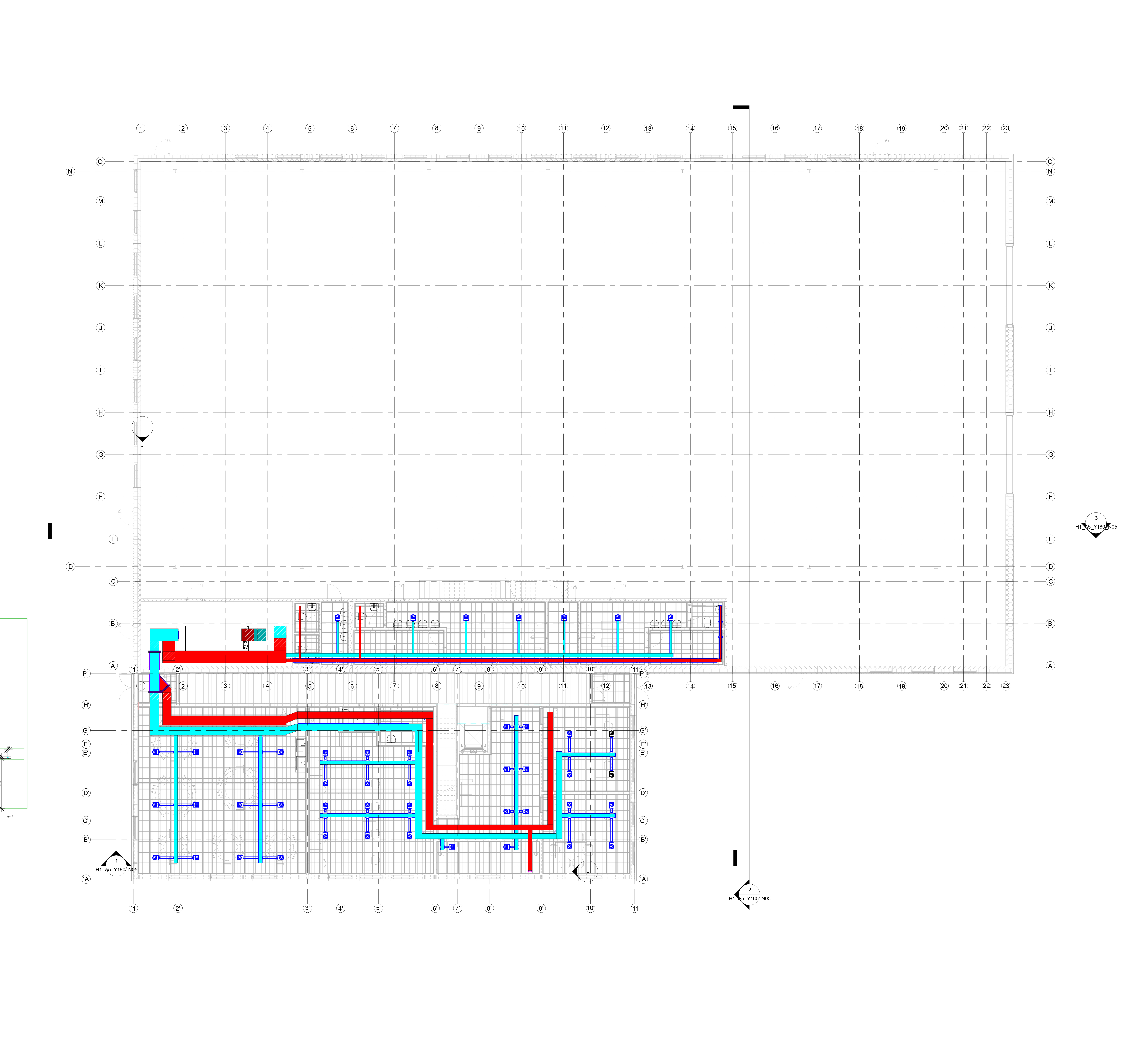
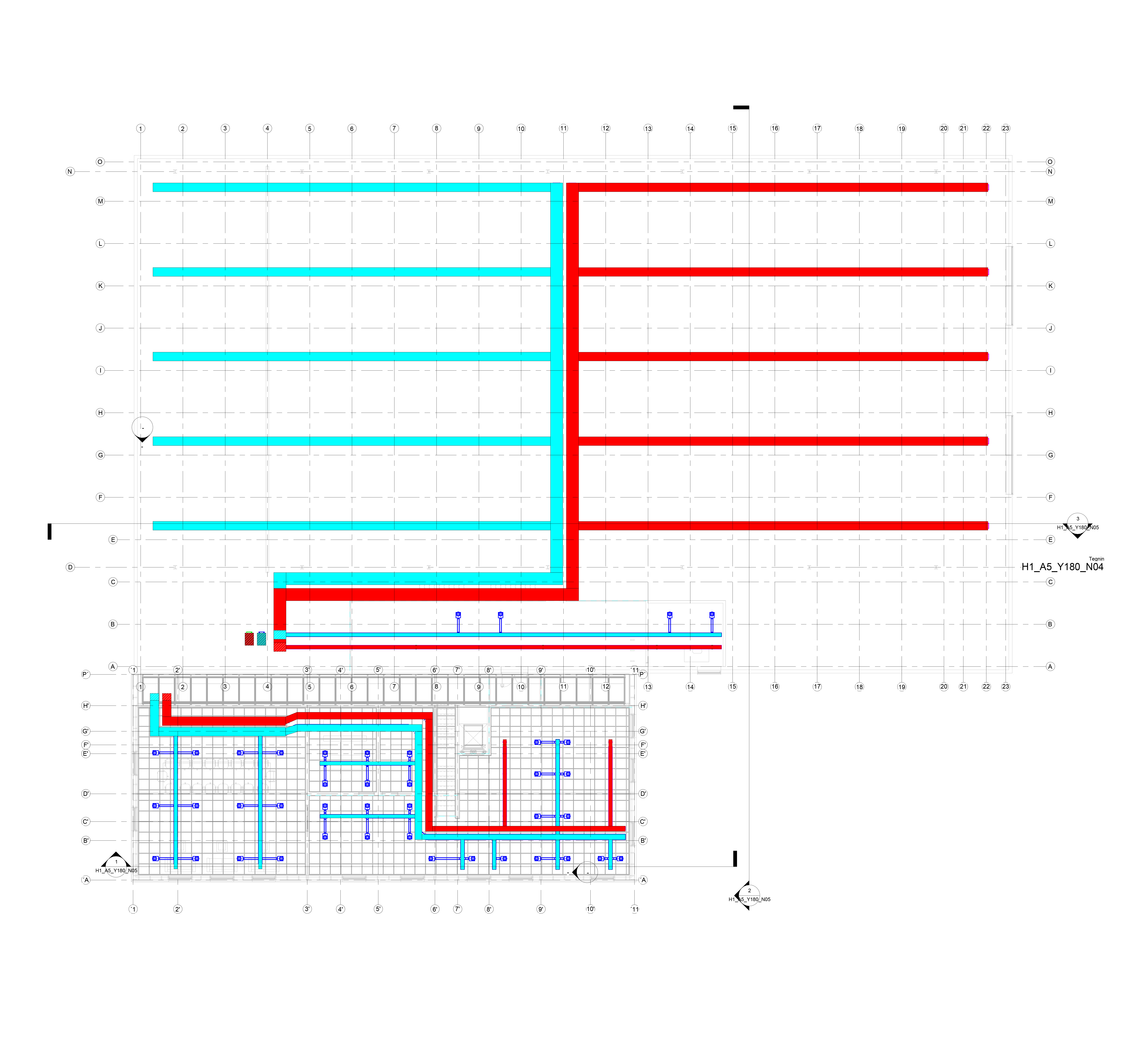
Ventilation Ground Floor
Ventilation 1st Floor Legend
Ventilation 1st Floor
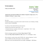
Tender Letter
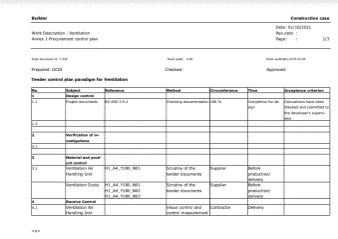
Tender Control Plan
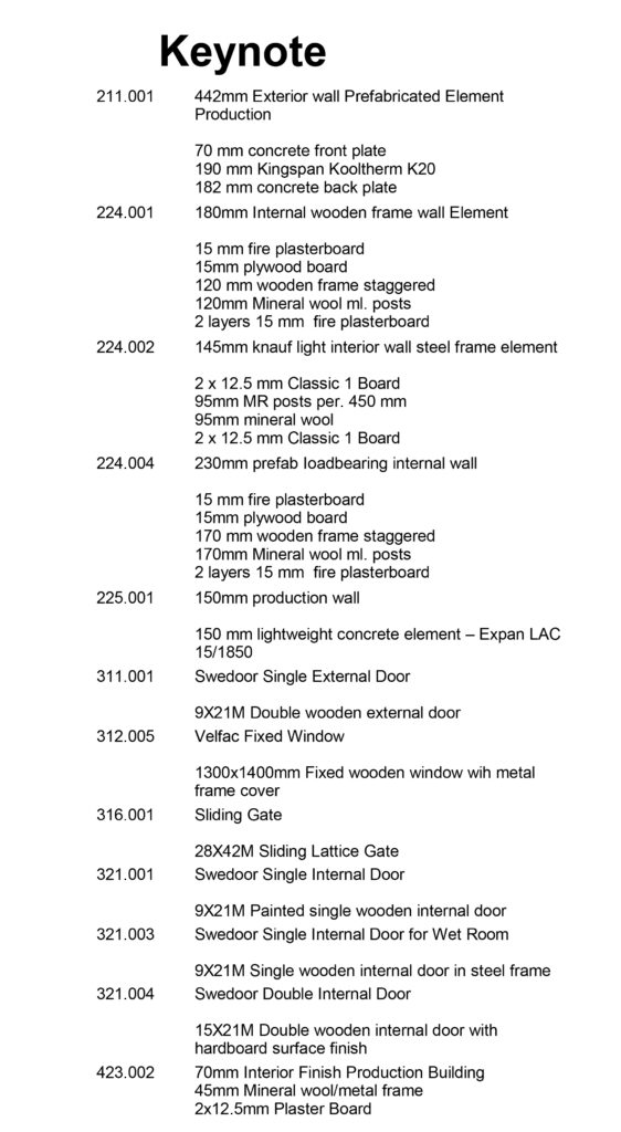
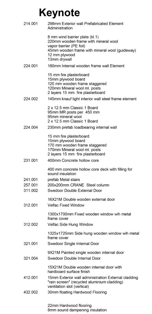
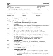
Parts Description

Details:

In Situ Main Section
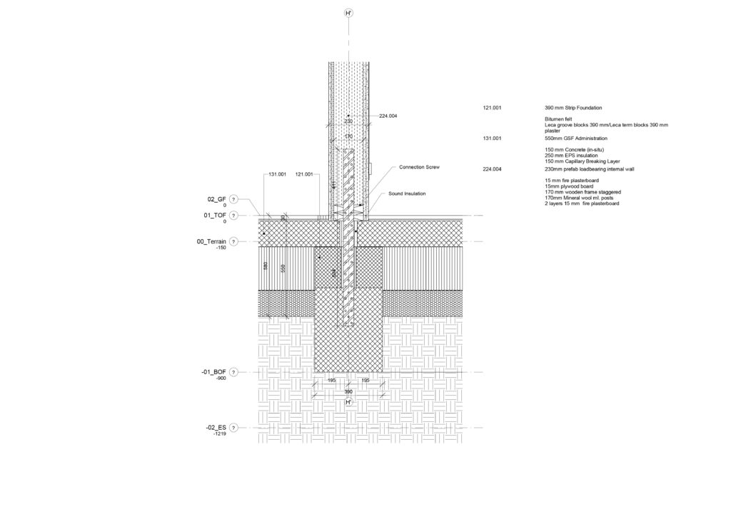
D1-Foundation + Exterior Wall Production Building
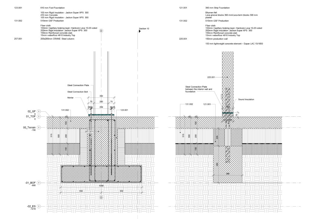
D2-Steel Column Foundation Detail and D3-Foundation and Interior Wall Detail
D4-Foundation and Interior Load-Bearing Wall Detail
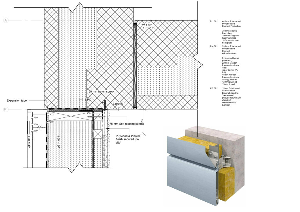
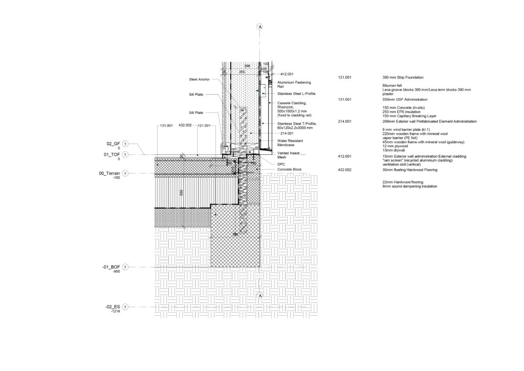
D5-Foundation + Exterior Wall Administration Details
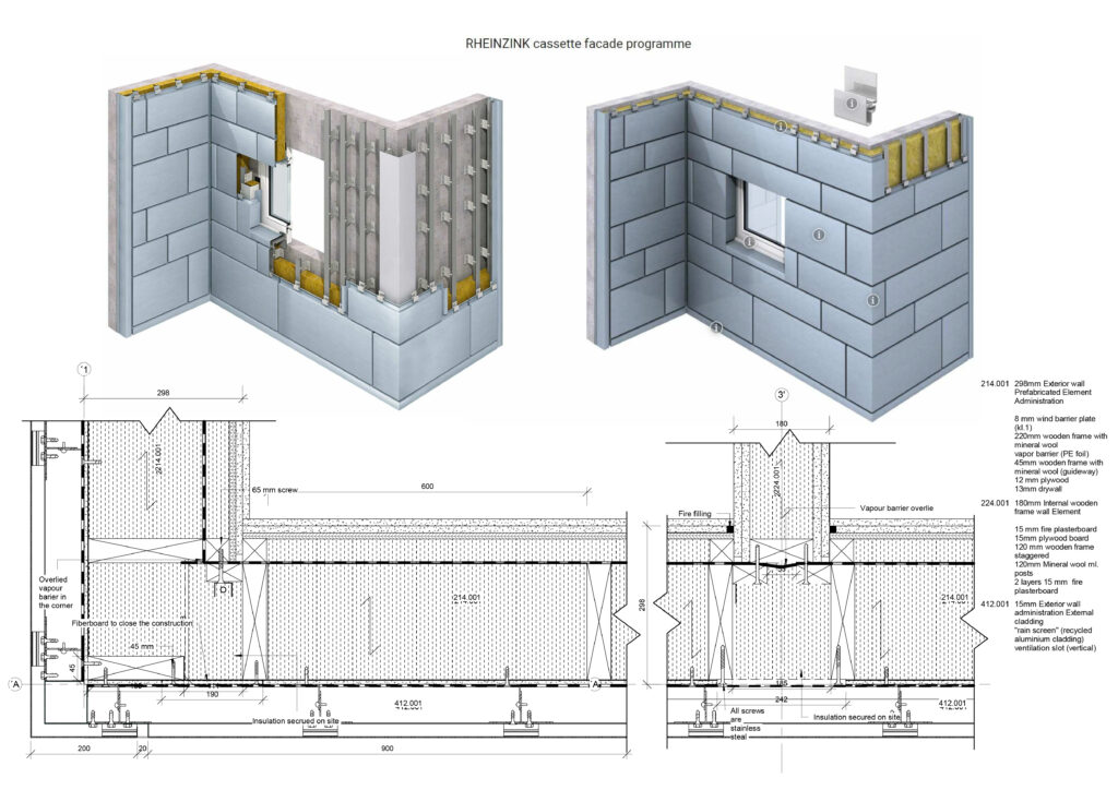
Cladding Corner and Production Building Wall Details and Reference
Cladding Detail
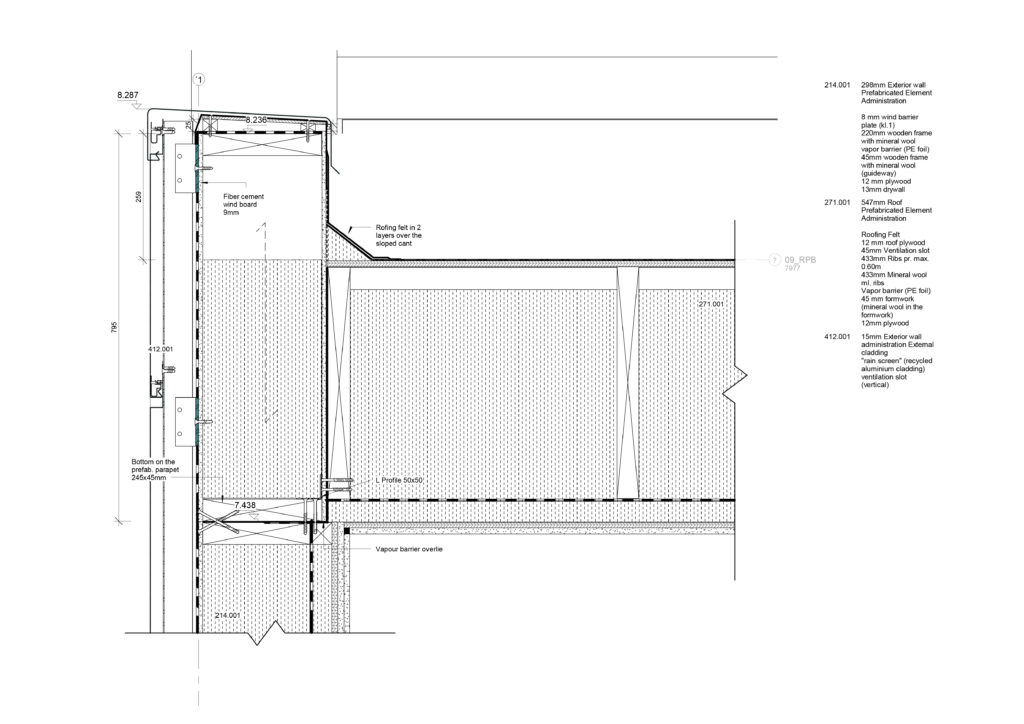
Cladding + Gable Wall Detail
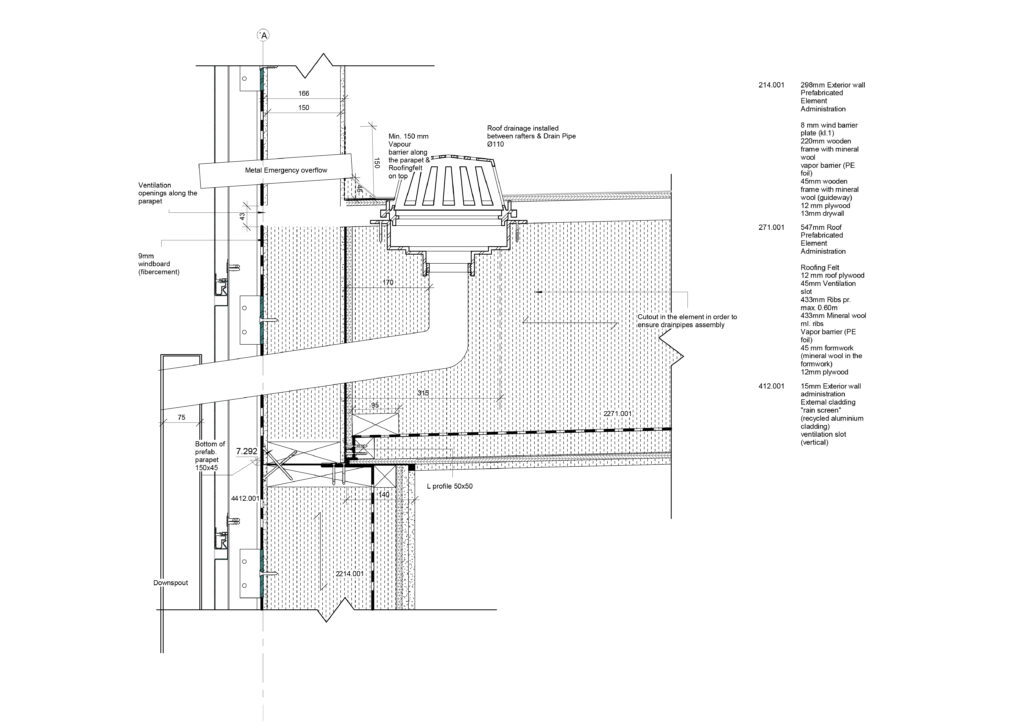
Cladding + Downspout Detail

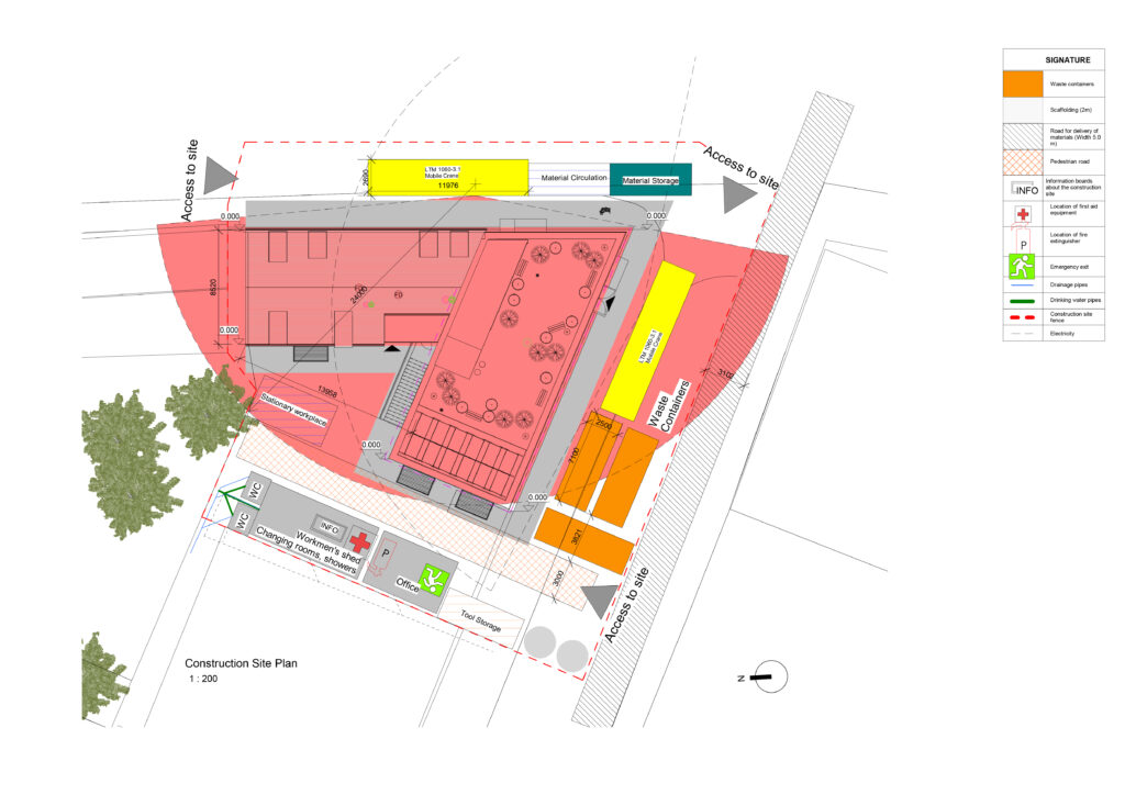
Construction Site Plan
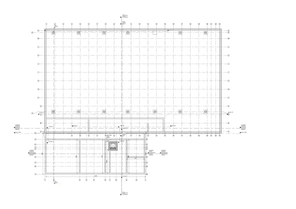
In Situ Top of Foundation Plan
In Situ Bottom of Foundation Plan

Multi-Storey Building for Residential and Commercial Use

  • Type of project: Architecture Technology, Construction Management, New Hybrid Building
  • Year: 2022
  • Software Used: Revit

The Project:

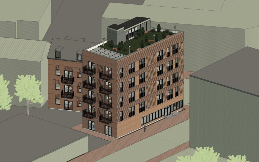
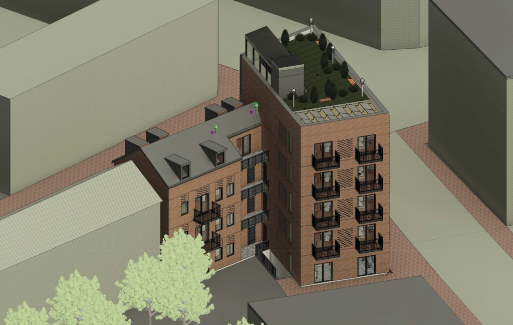
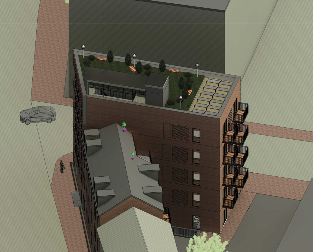
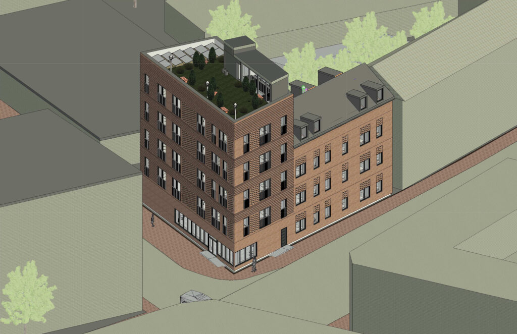
The overall theme for this project was to design a multi-storey building.
Because it was an interdisciplinary assignment, we were assigned different roles, mine being ICT Manager, Risk Manager, Engineer and Landscape Architect.
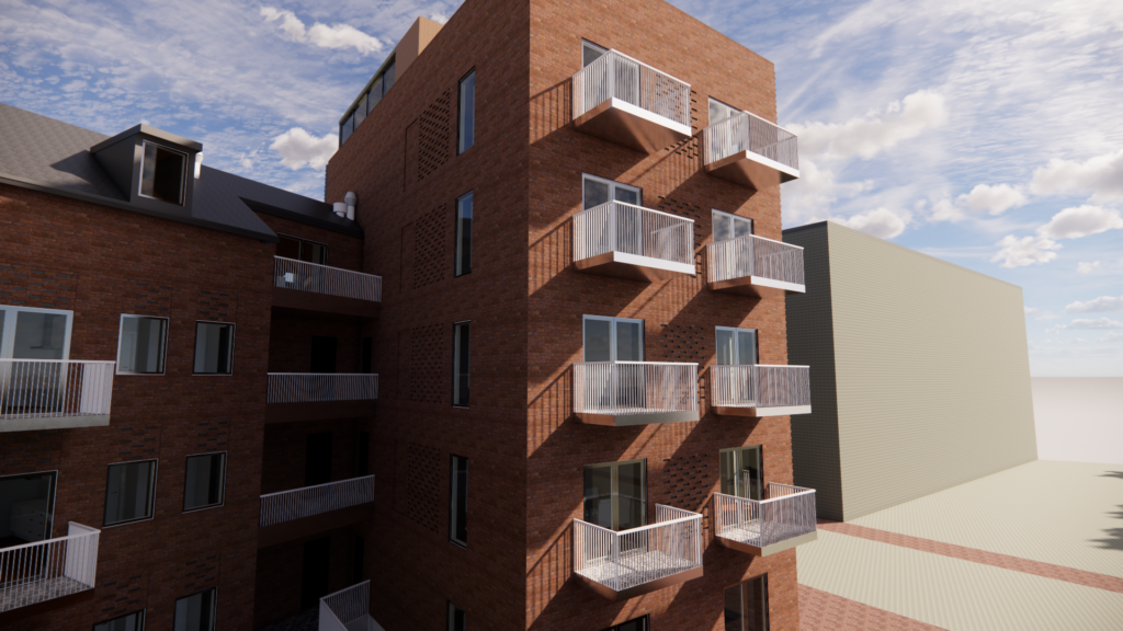
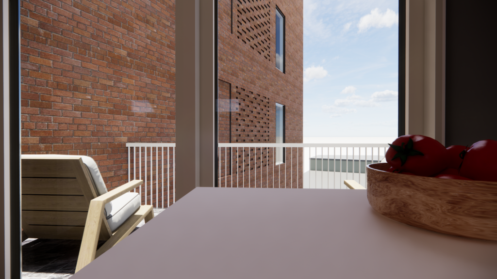
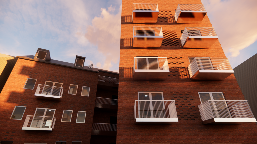
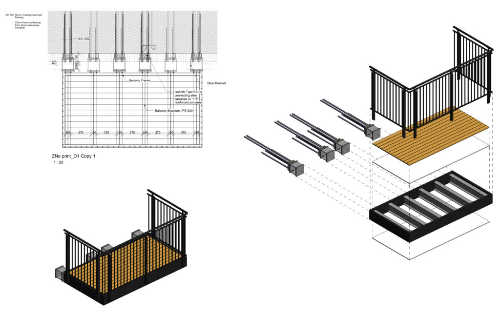
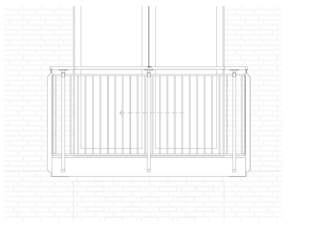
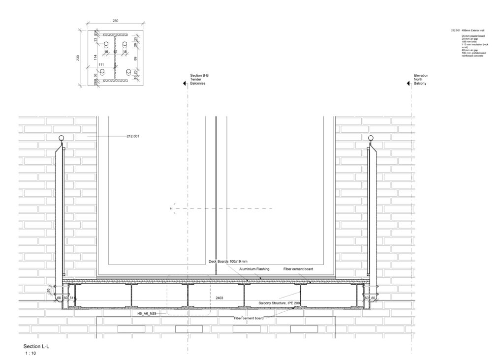
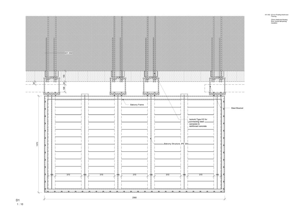
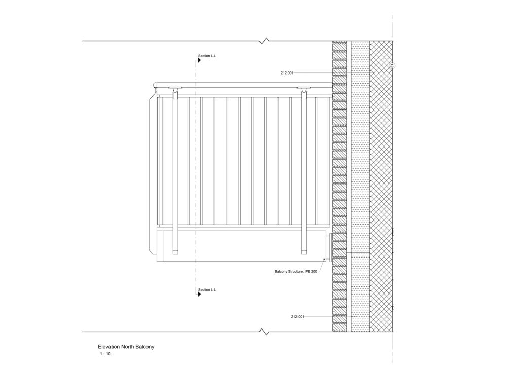
For my individual, I focused on balconies.

I was responsible for developing the following 3D Models:
Grid Model, Central Model, Landscape Model, Furniture Model and Ventilation Model. As the project was about designing a multi-storey building, I have gained valuable experience in working with linked models due to the changes that appeared constantly. Being passionate about BIM, I found this interesting and challenging.

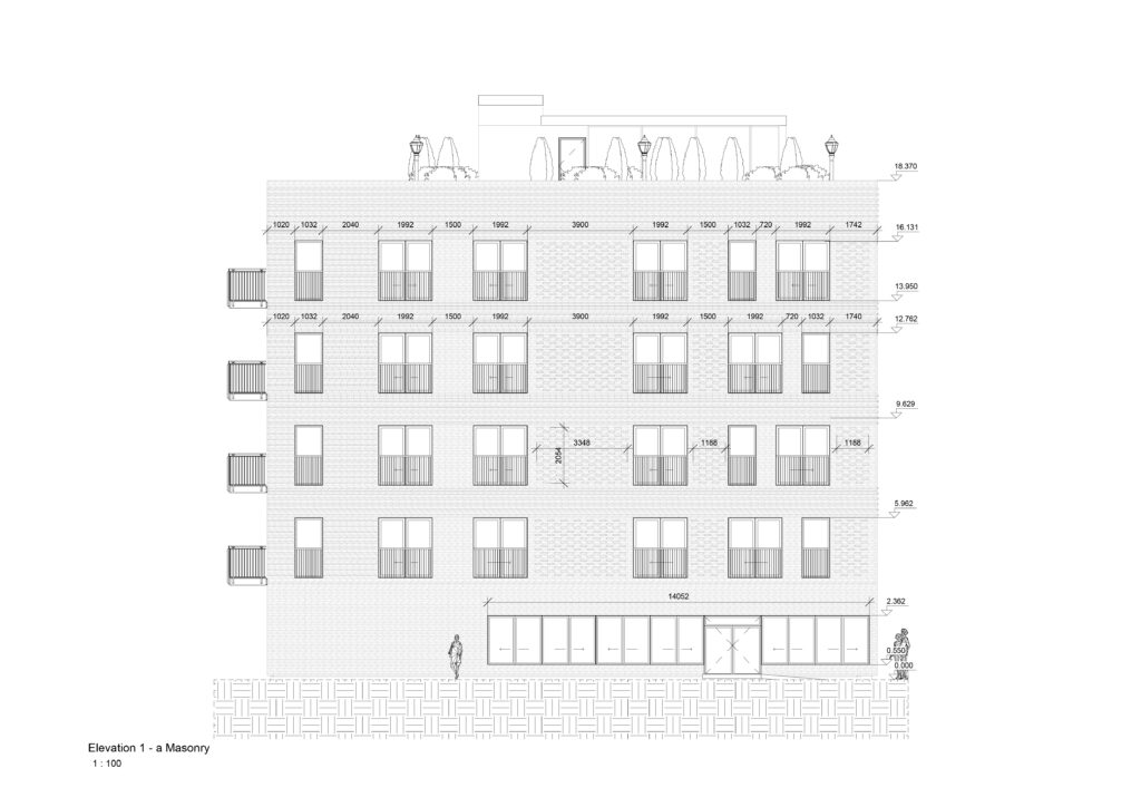
I was also responsible for developing the main architectural drawings that were used during the project for the three main outputs: Conceptualization, Project Proposal and Regulatory Project. The drawings are presented further on.

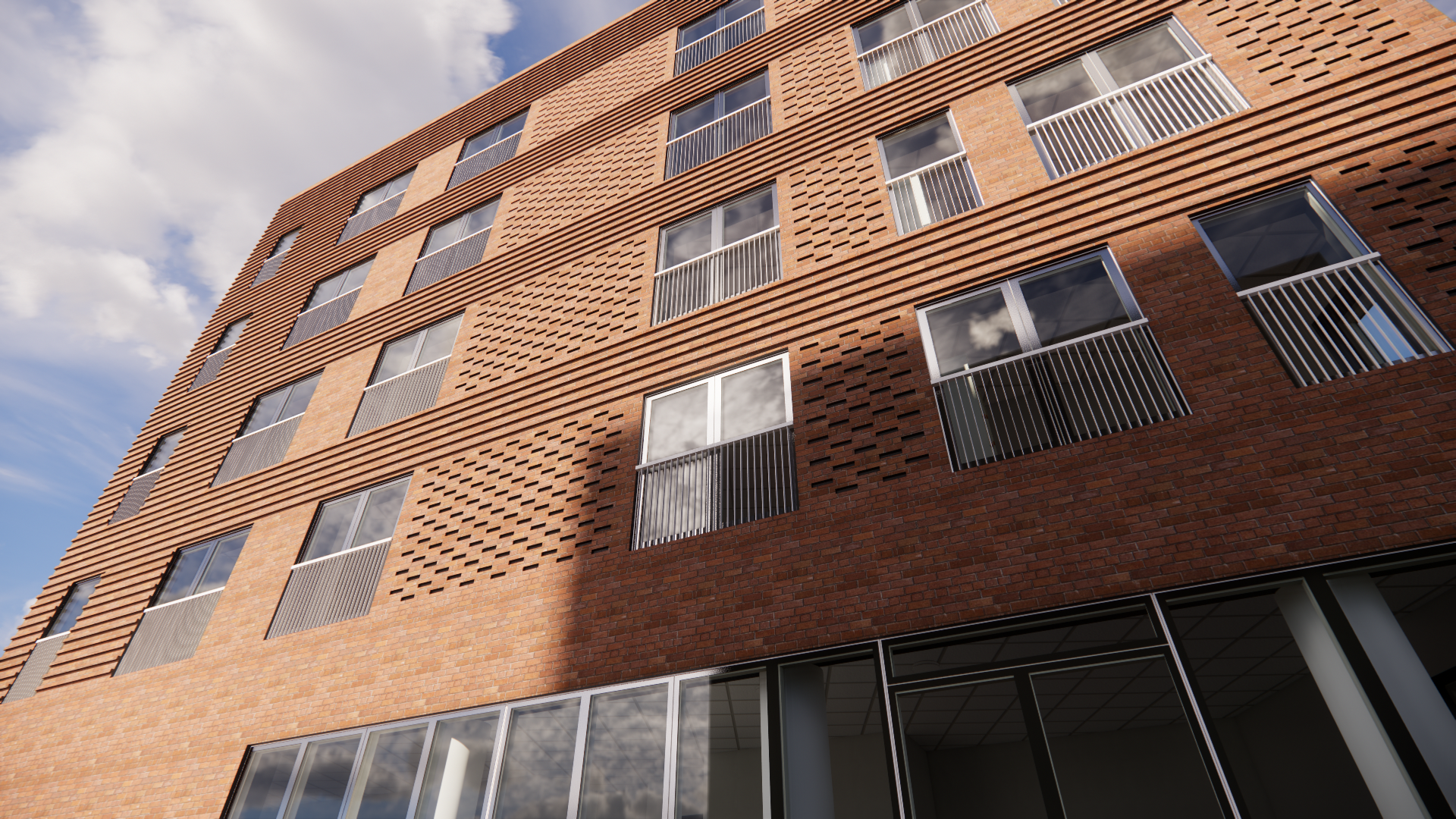
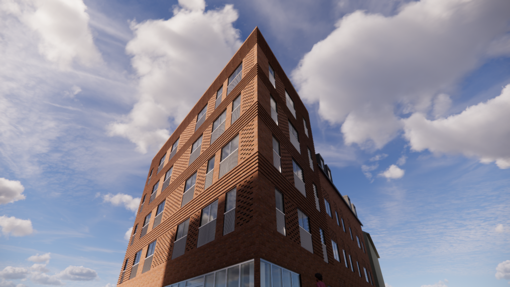
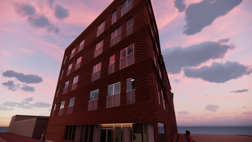
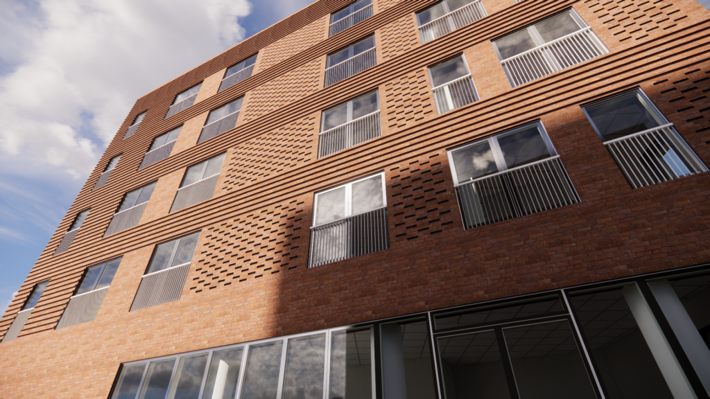
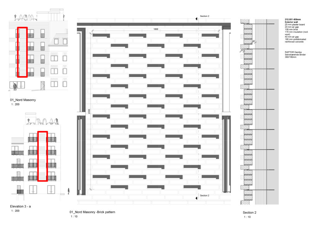
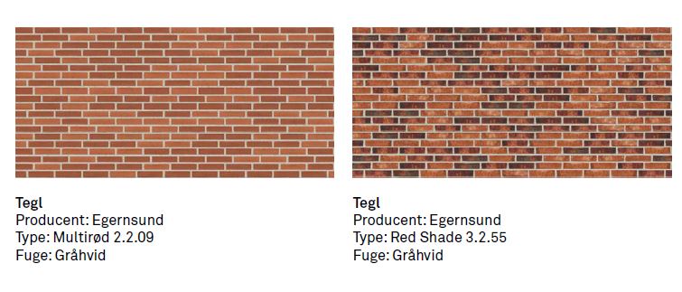
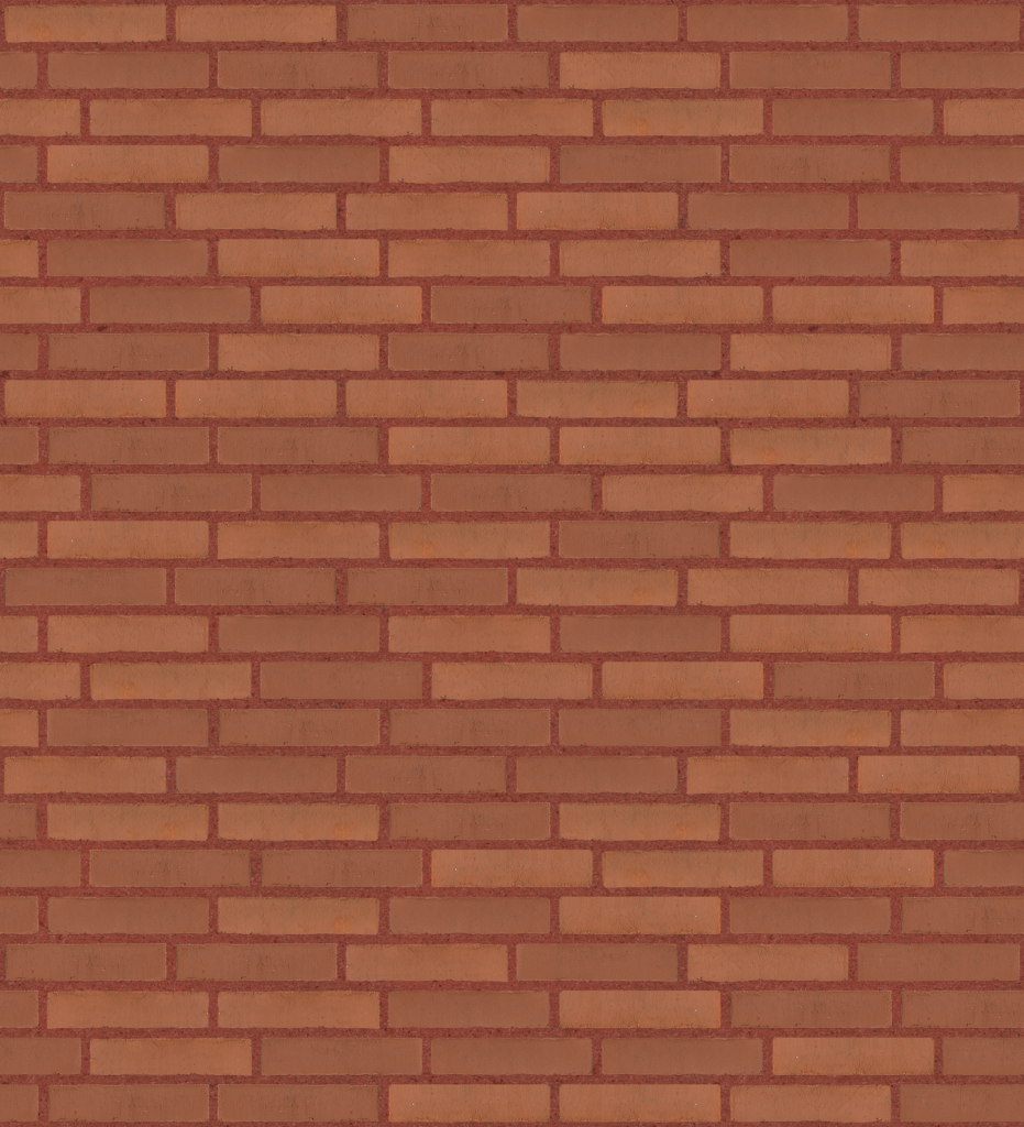
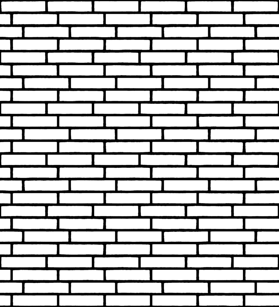
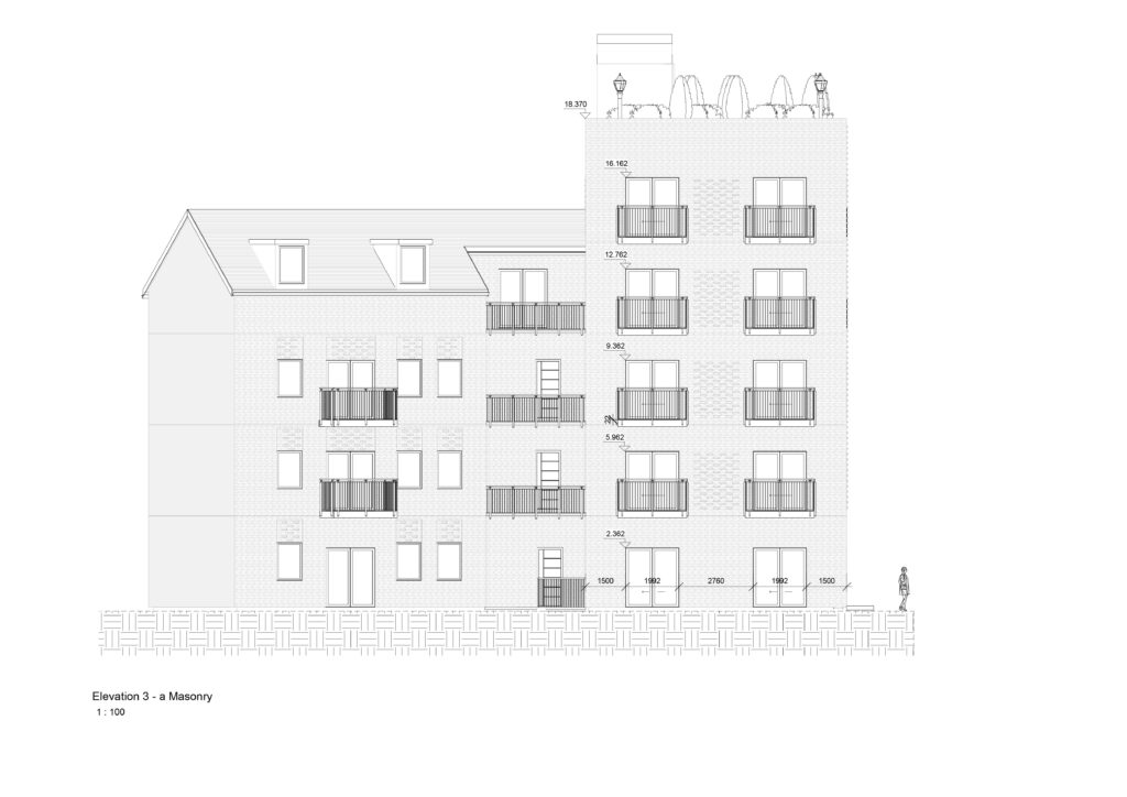
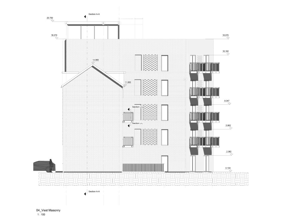
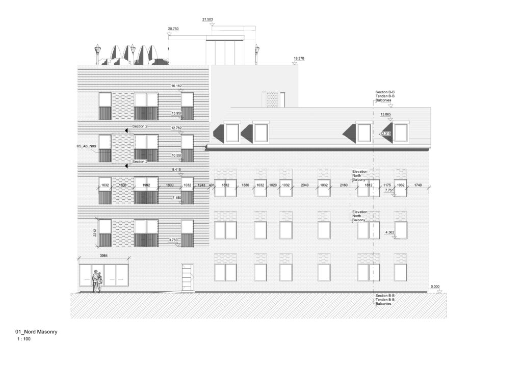
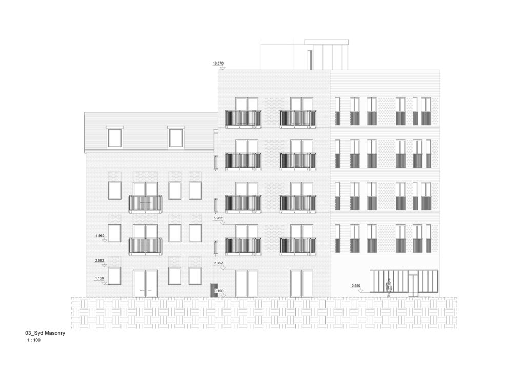
A part of the building modelling was about modelling the facade with a specific pattern and colour from a Danish manufacturer. I did this using pyRevit plugin for creating the pattern and therefore I modeled the inwards and outwards bricks all around the building.

Pattern Bricks
Elevation 1-a
Elevation 3-a
West Facade
North Facade
South Facade
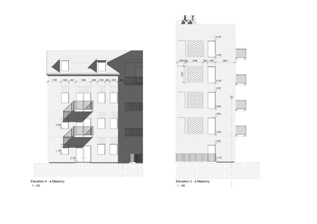
Elevation 4-a & Elevation 2-a
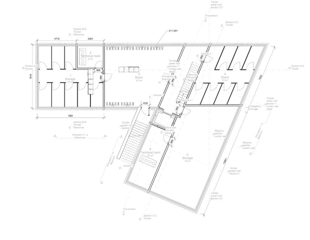
Basement
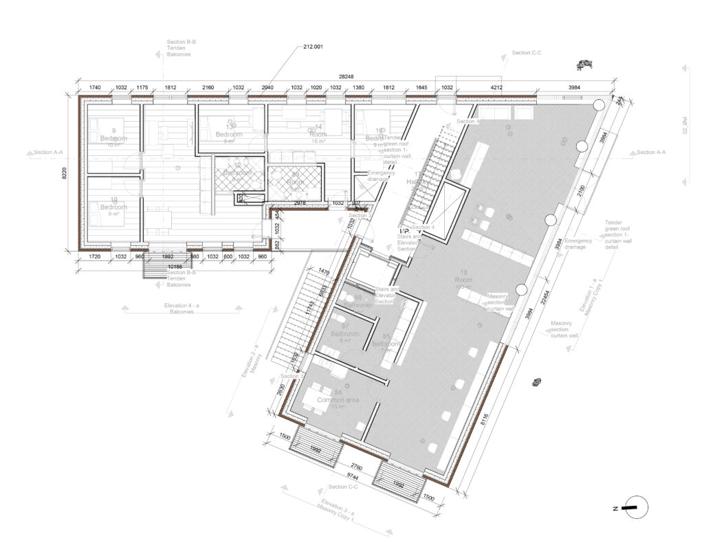
Ground Floor
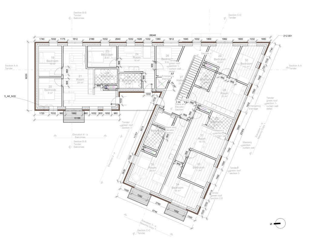
1st Floor
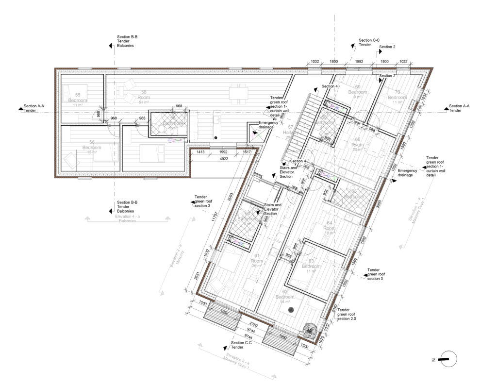
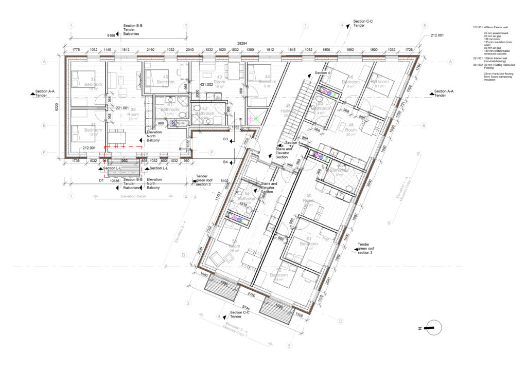
2nd Floor - Tender Plan
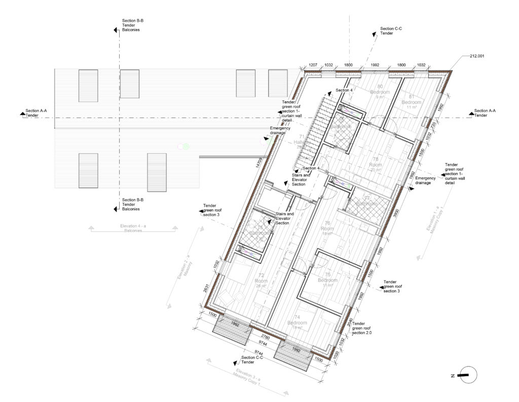
3rd Floor
4th Floor
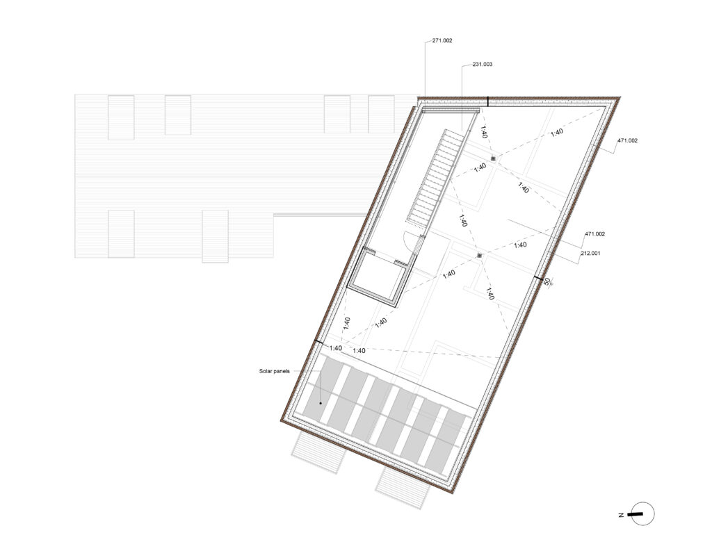
Roof
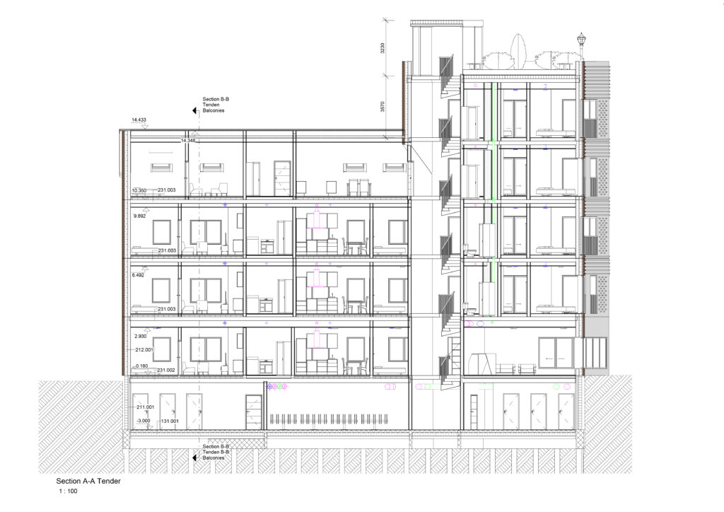
Section A-A Tender
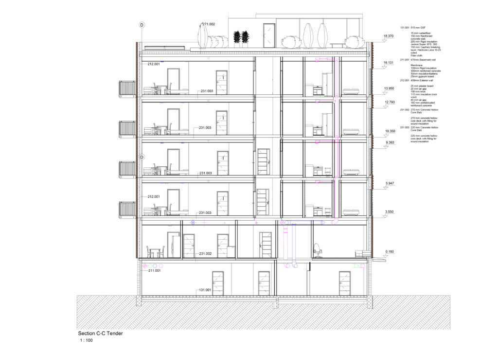
Section C-C Tender

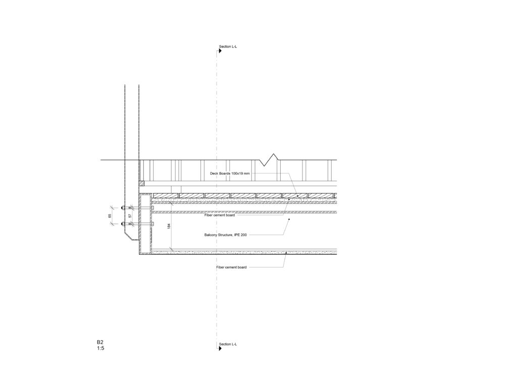
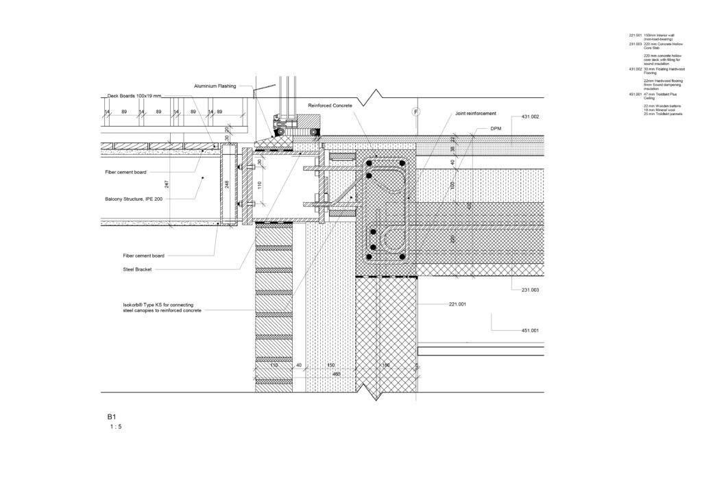
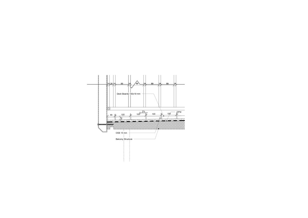
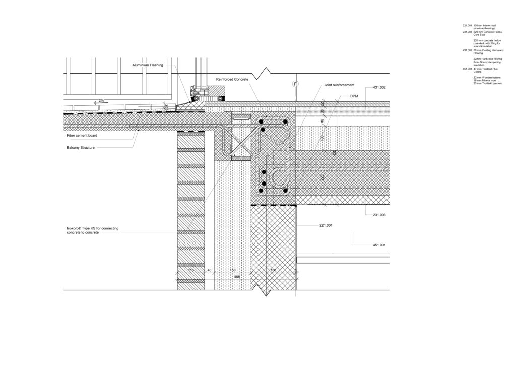
In Tender Design, I focused on two specific areas of interest consisting of balconies and ventilation, since these were subjects that I wanted to investigate and add to my previous experience in Architecture. To accomplish this, I prepared main drawings such as tender plans, facades and sections, supplemented by characteristic details.
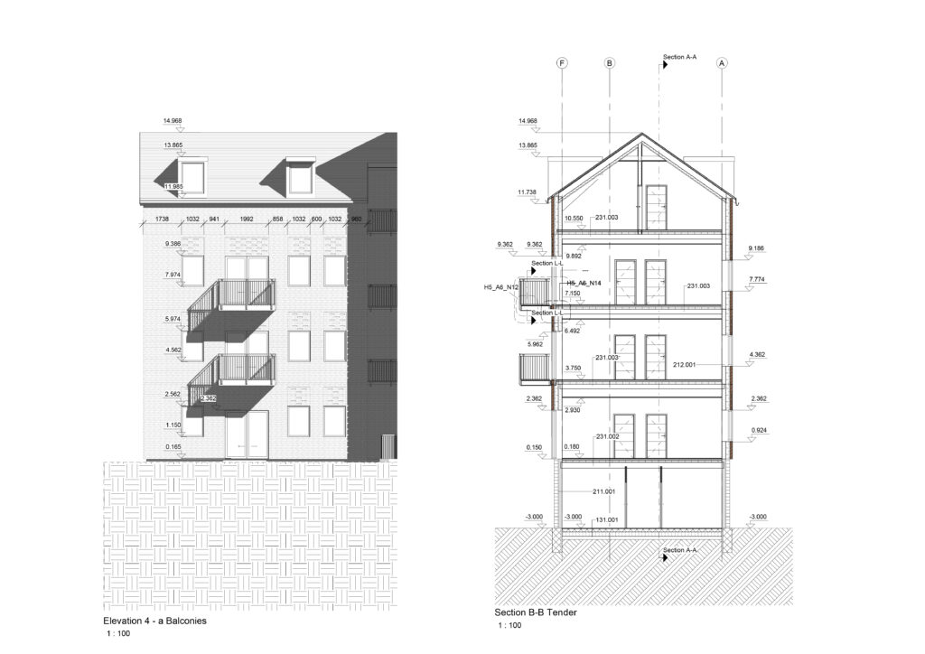
Elevation 4 - a & Section B-B Tender

Details:

Plan Tender Balconies
3D Detail Balcony
Elevation West Balcony
Section L-L
D1
Elevation North Balcony
B2
B1
B4
B3
Construction Site Plan

Dynamo and Ventilation:

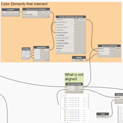
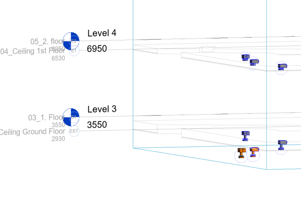
For my Elective Course subject, I decided to work on a Dynamo graph that helps aligning ceiling fixtures/air terminals to ceilings from a linked Revit model. In a lot of projects, there are changes that occur with the ceilings and my idea was to have an easy way to make the air terminals to be aligned with these ceilings, making it easier for MEP engineers to adapt their models with the linked ones.

Having in mind that during the design of the project there will inevitable be changes, I tried to determine what are the most important factors that will make this graph work without any issues. I have found some issues myself when worked on our previous project, so the study might be helpful for a lot of people who will find themselves in
similar situations.

The idea that I implemented was to collect all air terminals of a specific type of their category, while also collecting data about the offset of the ceiling level. When there are changes in the project with the ceiling, the one with MEP fixtures will be adapted easily by just running the script that will adjust the “Offset from Host” parameter values accordingly.

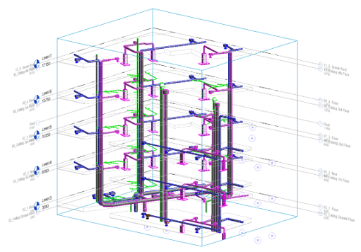
Ventilation Axonometry
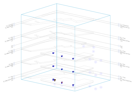
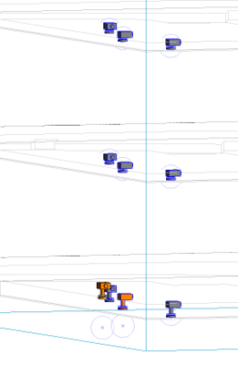
Unaligned Air Terminals
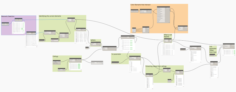
Dynamo Graph

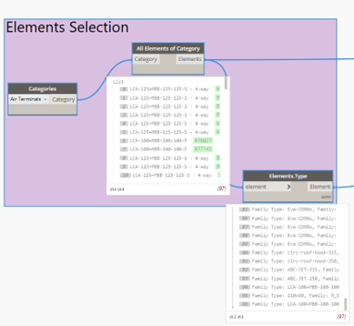
Selecting all elements of that category

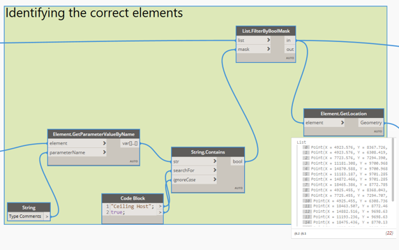
Identifying their location

Selection
Identifying

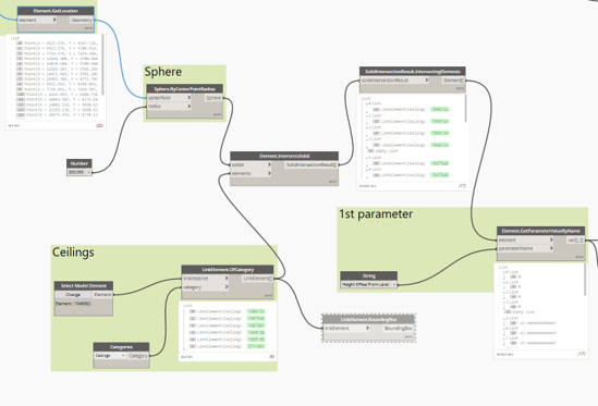
Creating spheres (cylinders can be used as well) using the location of the air terminals and then intersecting them with ceilings

Ceilings Intersecting Spheres

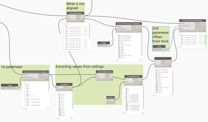
Creating Lists of the ceiling fixtures that are aligned/not aligned, extracting values for “Height Offset from Level” and “Offset from Host”, then coloring the ones not aligned, followed by adjusting the air terminals

List aligned/not aligned
Coloring elements
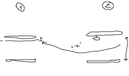
Sketch
Before the script
After the script